The Set-Up That I Used:
Materials:
- Circuit Board
- 12 volt power adapter
- Glass Beaker
- Three Test Tubes
- 2 68Ω Resistors (For current limiting)
- Electrical Wire
- Sodium Bicarbonate
- Test Tube Clamps and Stand
- Test Tube Stoppers
- Tooth Picks
 |
| Positive wire: RED Negative wire: BLUE |
 |
| Complete set-up |
 |
| Basic circuit set-up |
Procedure:
First off, I created a mixture of sodium bicarbonate and water. I mixed 200 mL of water and 7 grams of sodium bicarbonate together in an Erlenmeyer flask.
 |
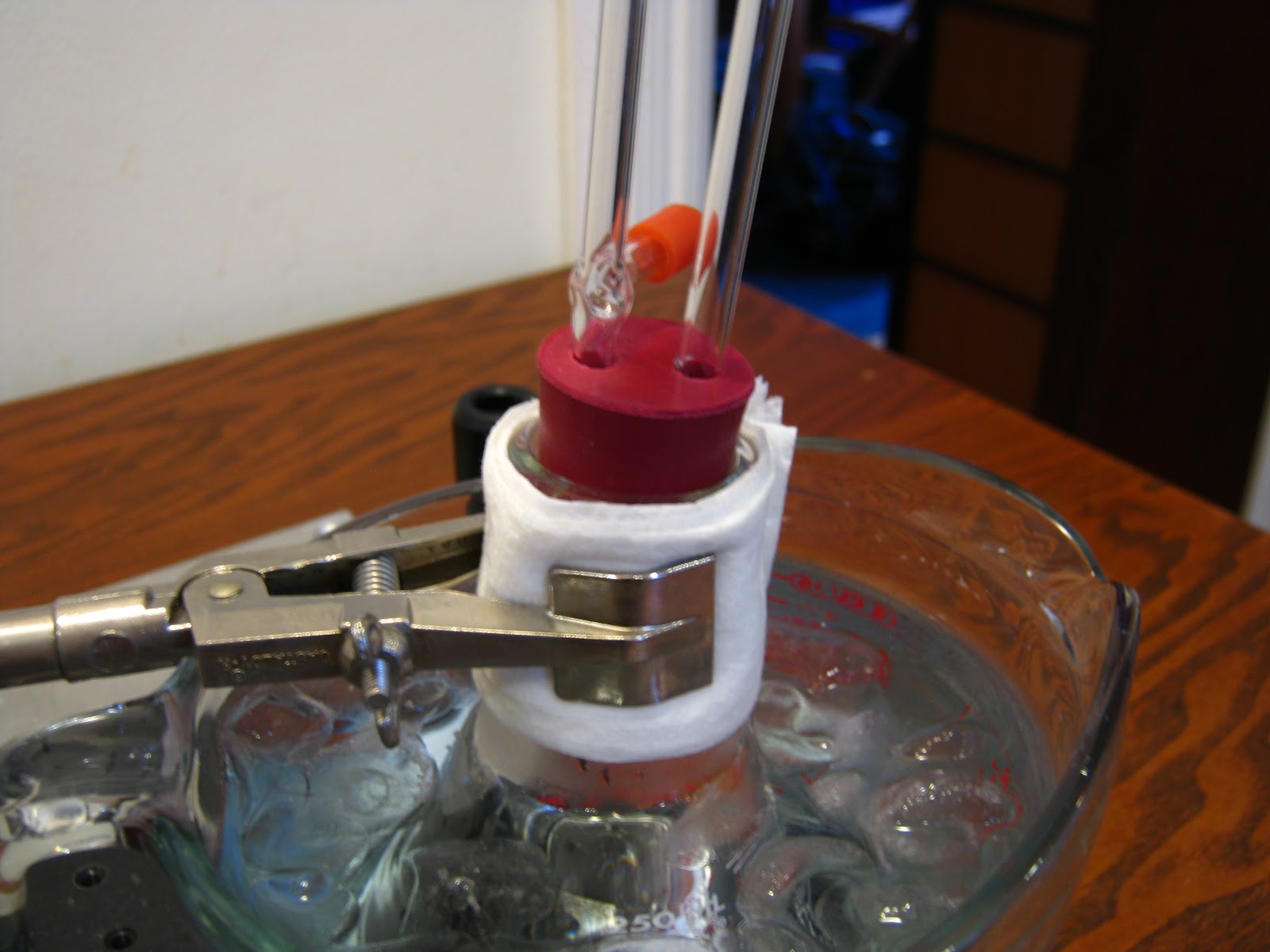
| Originally, the test tubes were completely filled with solution, but this photo was taken a little bit after the process started. |
Then, I filled the beaker with 100 mL of the solution. Taking one of the test tubes, I filled it up to the brim with solution, securely stopped it with my finger, inverted it, and lowered it into the beaker until it was submerged. Then I took my finger off and secured it to the test tube clamp. I did the same with a second test tube.
With the test tubes submerged, I positioned one over the anode and the other over the cathode. Next, I attached the anode and the cathode to the circuit-board, and bubbles started to form on the two wires submerged in the solution.
I noticed that the hydrogen formed more than two times as fast as the oxygen. I also noticed that the solution turned into a bluish color. These two facts are linked because I think that the blue was copper oxidation from the wires in the solution. For copper oxidation to take place, there needs to be oxygen, a solution, and a current for the copper atoms to combine with the oxygen atoms. That process reduced the amount of oxygen in the water that turned into gas.
When the tube over the cathode was filled with hydrogen, I took a test tube stopper, and with the top of the test tube still underwater, I sealed the test tube, unclamped it, and put it on a test tube rack. I then did the same with the oxygen, but because it was taking so long to fill up, I took it out of the solution when it was only about 1/5 full.
After I took them out of the solution and sealed them, I took the tube with hydrogen, lit a tooth-pick on fire, unplugged the hydrogen test tube (see video below), and put the flaming tooth pick over the mouth of the test tube. When I put the flaming tooth-pick over the mouth of the test tube, it went "pop!" and the tooth-pick flared up a bit. I did the same thing with the oxygen but instead of a flaming tooth-pick, I blew out the tooth-pick and wile it was still glowing I thrusted it into the test tube. Unfortunately, because there was not enough oxygen I think, nothing happened. However, when I reopened the oxygen and thrust in a flaming tooth-pick, if you look closely at the video you can see that the flame brightens for a second while it is close to the solution. Finally, I did the same with the mixture of hydrogen and some oxygen that I created by collecting both gases during the electrolysis. It went "POP!" almost immediately after getting in contact with the fire, and the pop it made was louder than the one the hydrogen test tube made. Also, the test tube that contained the hydrogen-oxygen mixture got considerably hot after the gas inside ignited – which did not happen for the test tube containing only hydrogen.
I noticed that the hydrogen formed more than two times as fast as the oxygen. I also noticed that the solution turned into a bluish color. These two facts are linked because I think that the blue was copper oxidation from the wires in the solution. For copper oxidation to take place, there needs to be oxygen, a solution, and a current for the copper atoms to combine with the oxygen atoms. That process reduced the amount of oxygen in the water that turned into gas.
 |
| Test tube filled with "Hydrogen!" |
After I took them out of the solution and sealed them, I took the tube with hydrogen, lit a tooth-pick on fire, unplugged the hydrogen test tube (see video below), and put the flaming tooth pick over the mouth of the test tube. When I put the flaming tooth-pick over the mouth of the test tube, it went "pop!" and the tooth-pick flared up a bit. I did the same thing with the oxygen but instead of a flaming tooth-pick, I blew out the tooth-pick and wile it was still glowing I thrusted it into the test tube. Unfortunately, because there was not enough oxygen I think, nothing happened. However, when I reopened the oxygen and thrust in a flaming tooth-pick, if you look closely at the video you can see that the flame brightens for a second while it is close to the solution. Finally, I did the same with the mixture of hydrogen and some oxygen that I created by collecting both gases during the electrolysis. It went "POP!" almost immediately after getting in contact with the fire, and the pop it made was louder than the one the hydrogen test tube made. Also, the test tube that contained the hydrogen-oxygen mixture got considerably hot after the gas inside ignited – which did not happen for the test tube containing only hydrogen.
| Oxygen test tube |
| Hydrogen test tube |
| Mixture of Hydrogen and some Oxygen |
Additional Results

 I did some additional experiments aimed at studying the effects of the electrolysis process on the metal of the cathode or of the anode. To do so, I used several coins (quarter, nickel) and a wrench. The coins formed very rapidly a green/blue substance when used as the anode, which I think is some oxide of copper. The wrench did not do that, instead, it got kind of corroded when used as the anode. Any of those objects, used as the cathode, got plated with copper. But if they were left in the solution for too long, they acquired a black coating over the copper plating. By the way, the fact that the quarter and the dime both produced a large quantity of green substance means that they are made of copper! In fact, Wikipedia says that quarters and nickels are made up of about 90% copper!